电子元器件产业互联网平台
电子元器件产业互联网平台


一站式电子元器件采购平台

元器件移动商城,随时随地采购

半导体行业观察第一站!

专注电子产业链,
坚持深度原创

电子元器件原材料采购
信息平台
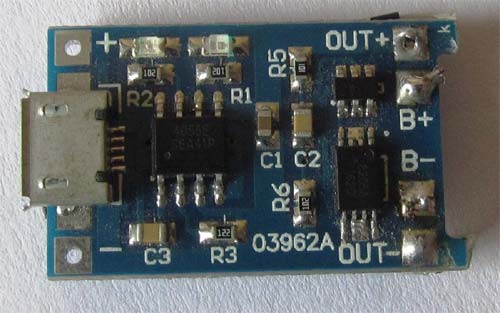
摘要: 该模块最常用于所有涉及锂离子电池的项目。众所周知,锂电池不应过度充电或过度放电,因此该模块将在充电和放电期间监控电池的电压水平。如果这些值超过临界值,模块将自动断开电路并保护电池。
该模块最常用于所有涉及锂离子电池的项目。众所周知,锂电池不应过度充电或过度放电,因此该模块将在充电和放电期间监控电池的电压水平。如果这些值超过临界值,模块将自动断开电路并保护电池。
.jpg)
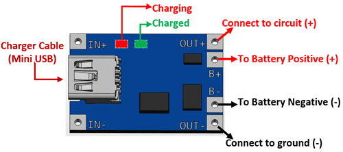
| Pin Number | Pin Name | Description |
| 1 | OUT + | This pins outputs the positive voltage from battery. It should be connected to the circuit which has to be powered by the battery |
| 2 | B+ | Outputs positive voltage from USB cable to charge to battery. It should be connected to the positive of the battery |
| 3 | B- | Outputs negative voltage from USB cable for charging battery. It should be connected to negative of the battery |
| 4 | OUT - | This pin outputs negative voltage from battery. It should be connected to the ground of circuit which has to be powered by the battery |
| 5 | IN + | Should provide +5V, can be used if charge cable not available |
| 6 | IN - | Should provide ground of the +5V supply, can be used if charge cable not available |
| 7 | LED Red | This LED turns on while the battery is charging |
| 8 | LED Green | This LED turns on after the battery is fully charged |
使用锂电池时务必要小心。该模块以5V工作,该电压可由通常用于为智能手机充电的USB mini电缆提供。您可以使用任何类型的移动充电器及其电缆为该模块供电。如果您打算在不使用电缆的情况下直接为其供电,则+ 5V应连接至IN +,而IN –应接地。
如上面的引脚图所示,应连接锂离子电池。该模块没有反极性保护,因此在连接电池时请务必小心。使用万用表检查电池的极性,如果反向连接,模块将立即变热,这很可能会杀死它。如果正确连接且充电器已打开,则红色指示灯将变高,表明电池正在充电。充电过程由TP4056线性电压IC控制,其电路图如下所示(保护电路未显示)

默认情况下,模块的充电电流为1A,可以通过调节电路图中所示的电阻R PROG(模块上的R3)进行控制。相同的更多详细信息,请参见下面给出的TP4056数据表的数据表。
一旦模块为锂电池充满电,它将自动停止充电,并且红色LED指示灯将熄灭,绿色LED指示灯将点亮以指示已完成。现在,电路可以连接到必须由该电池供电的电路(负载),如上面的引脚图所示。模块将监视电路(负载)消耗的电池电压。当其低于临界值(3.7V)时,模块将自动从负载上断开电池的连接,并防止电池过放电。
锂电池充放电
常用于18650锂离子电池
便携式电子
移动电源
与5V升压器配合使用为Arduino项目供电

社群二维码

关注“华强商城“微信公众号
Copyright 2010-2023 hqbuy.com,Inc.All right reserved. 服务热线:400-830-6691 粤ICP备05106676号 经营许可证:粤B2-20210308